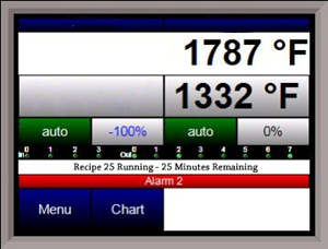
9130 Controller with Data Logging
<class=””>
The 9130 is a universal programmable temperature controller used for single loop control, addressing the need for data logging and recipe/timer thermal process applications.
<class=””></class=””></class=””>

| Touch Screen Interface |
| Digital Data Logging for Flash Card - Built-in Paperless Recording |
| 300 24-Step Recipes |
| DIN Rail Mount |
| 8 Relay Contacts |
| 24VDC (Power Supply Included) |
| Analog Outputs - PV Retransmission |
| Multiple PIDs |
| Overshoot Suppression Logic |
| Auto Tuning |
| Three (3) RS485, Two (2) RS232, Ethernet |
| 4-20mA Current Control Output |
| Three (3) Isolated Inputs |
| Timer options allow for configuration for flexible management of process control |
|---|
Configurable start modes
|
Configurable control modes
|
| User configured acknowledgement |
Digital input control
|
| Software Included: |
|---|
| TS Manager - Data management for touch screen flashcard. Remote data viewer, historical data backup, SuperDATA integration. |
| Configurator - Remote setup and configuration of controller. |
| Recipe Management, Opcodes Include: |
|---|
| Ramp at rate |
| Guarantee soak on control and active load thermocouple |
| Delay time |
| Thermocouple temperature inquiry |
| Remote setpoint to slave instruments |
| Branch and jump to other programs |
| Limit control output |
| Change PID settings |
This message is generated when the HMI does not have communications to the controller inside the panel. Possible reasons for this include:
Loss of 24VDC power to terminals 1 (-) and 2 (+) on the controller.
A bad communication cable between the HMI and the controller.
(Check by ringing out the cable end to end, or checking for continuity.)
Bad connection between the HMI and the controller.
(Check both ends to make sure they are securely connected and not loose or damaged.)
Cable connected to wrong port on back of HMI.
(COM1=232 and COM3=485)
SOAK is simply a specified amount of time. There are no conditions required for the timer to count down.
G_SOAK is also a soak timer, but it will only run when pre-set conditions are met and maintained. If conditions are not met, the timer is placed in hold status.
See our Schematics and Drawings Page for wiring info.
Navigate to “Slave Instrument Setup” (This may involve logging in).
Select an instrument you want to configure and tap “Edit.” Note that the list of available instruments is color coded:
Blue=atmosphere
Red=temperature
Yellow=events
White=user-selected instrument
Configure the instrument, address, and port. Note the following:
All devices on the same slave port must utilize the same protocol.
An address of zero (0) will disable the instrument.
Controllers that provide dual functions must have the same address assigned for both.
If your instrument is not shown in the list, use User Instruments 1-16 along with the Generic Instrument Setup menu (see manual for additional details).
Slave 1 = terminals 5 (-) and 6 (+)
Slave 2 = terminals 22 (+) and 23 (-)
RS-232 = 9-pin port on controller’s face


